
Boeing 737 MAX: When a Single Sensor Becomes a Critical Point of Failure
A modern commercial airliner relies on more than mechanical systems or software code alone; its safety depends on continuous integration between aerodynamics, sensors, flight control computers, actuators, and the flight crew. This makes the Boeing 737 MAX accidents one of the most critical case studies in modern systems engineering. At the center of this investigation was the MCAS function, whose architecture allowed a single erroneous sensor input to initiate an uncommanded sequence of automated flight control inputs.
1. What Does the Aircraft Actually Measure?
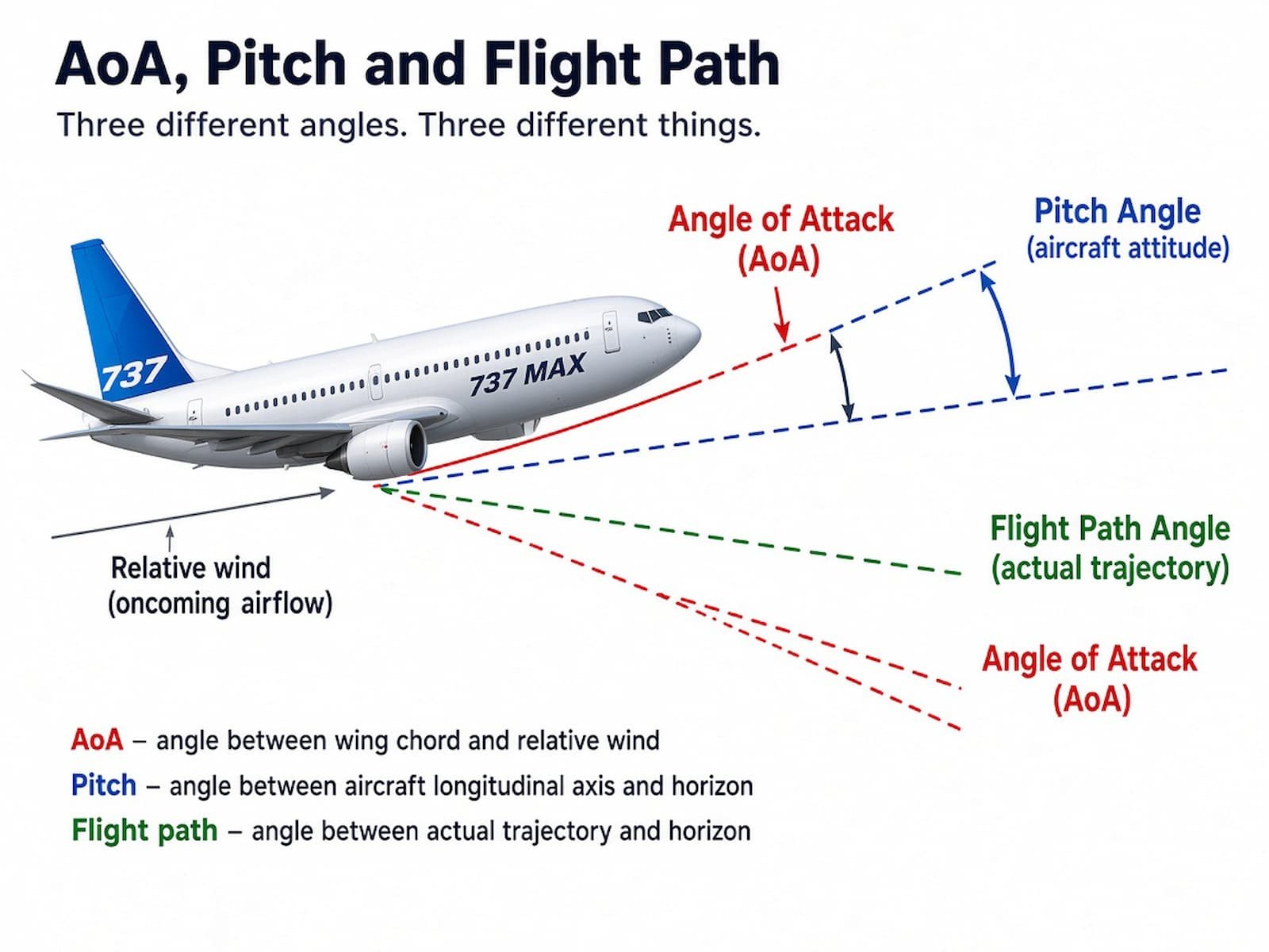
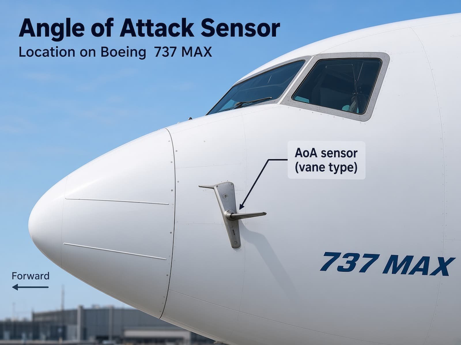
To understand the physical principles involved, a fundamental aerodynamic concept must be established. An aircraft operates in a dynamic atmosphere where wind gusts, turbulence, and airspeed changes continuously alter the direction of the oncoming airflow. Flight control systems rely heavily on the Angle of Attack (AoA)—the angle between the wing chord line and the direction of the relative wind. Vane-type AoA sensors mounted on the forward fuselage serve strictly as measuring instruments: they do not process decisions, but merely send raw electrical signals to the flight computers.
2. Why Does an Aircraft Need Angle of Attack Data?
An aircraft wing operates within specific aerodynamic limits. As the angle of attack increases, lift increases up to a critical point. Exceeding the critical AoA leads to airflow separation over the upper wing surface, resulting in an aerodynamic stall. To maintain proper flight envelope protection and control functions, the flight computer requires reliable real-time aerodynamic state data.
3. Why Two Sensors Do Not Guarantee Safety by Default
The Boeing 737 MAX is equipped with two AoA vanes—one on the left side and one on the right side of the nose section. The logic of having two independent sensors is clear: if one sensor records an abnormally high angle while the other indicates normal parameters, the resulting discrepancy signals a failure. A fundamental principle of safety systems engineering dictates that a single sensor input must not be treated as an absolute truth. However, in its initial implementation, MCAS processed input from only one of the two AoA sensors during any given flight.
4. Elevator vs. Horizontal Stabilizer: What Is the Difference?
The empennage of the aircraft features two distinct control surfaces: the Elevator—a movable hinged surface on the trailing edge used for immediate pitch control via column inputs, and the Horizontal Stabilizer—a large adjustable surface that changes overall aerodynamic trim. The elevator responds instantaneously to pilot control column movement, whereas the horizontal stabilizer adjusts the baseline aerodynamic force required to maintain pitch trim.
5. Why Was MCAS Implemented?
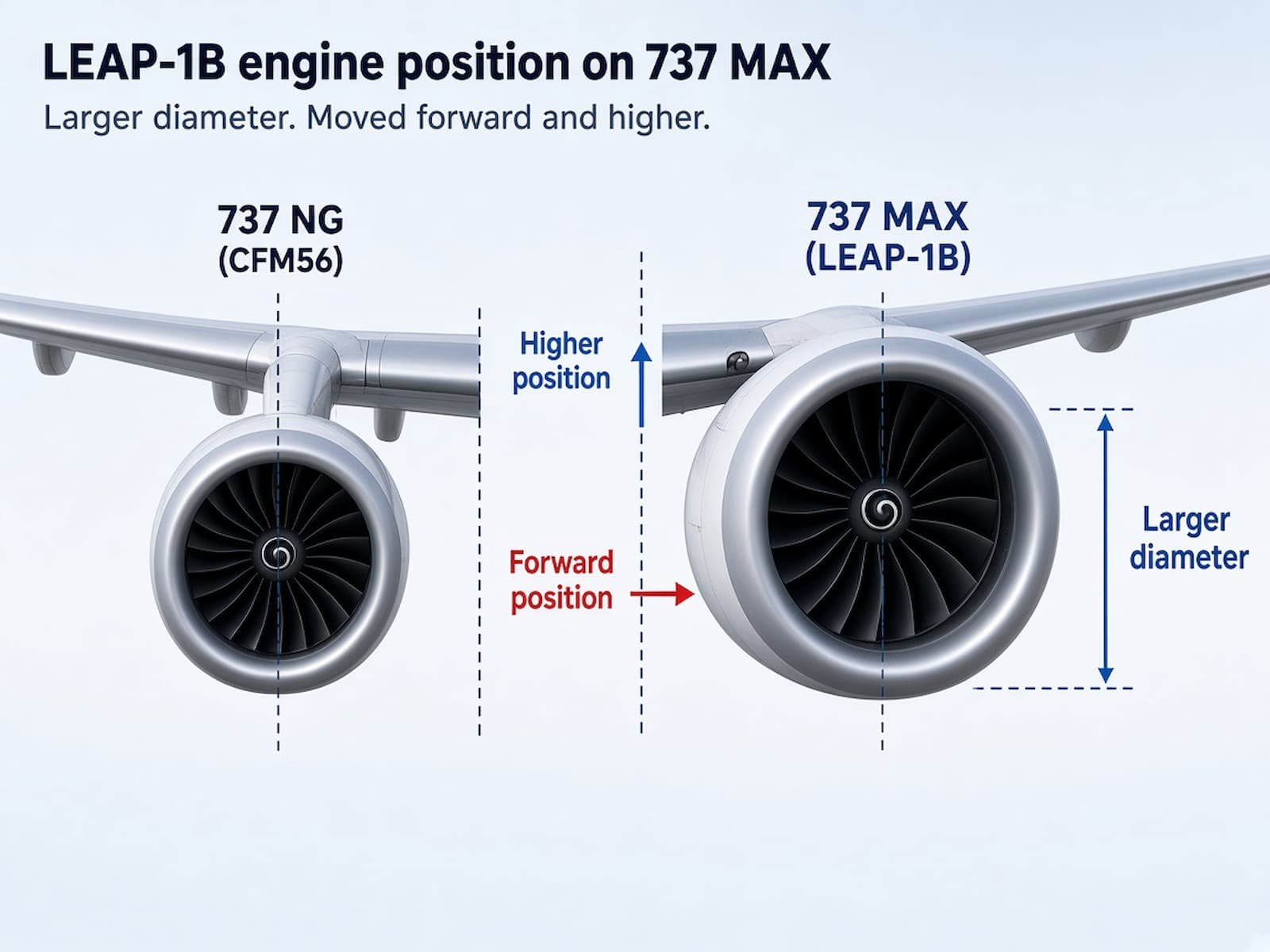
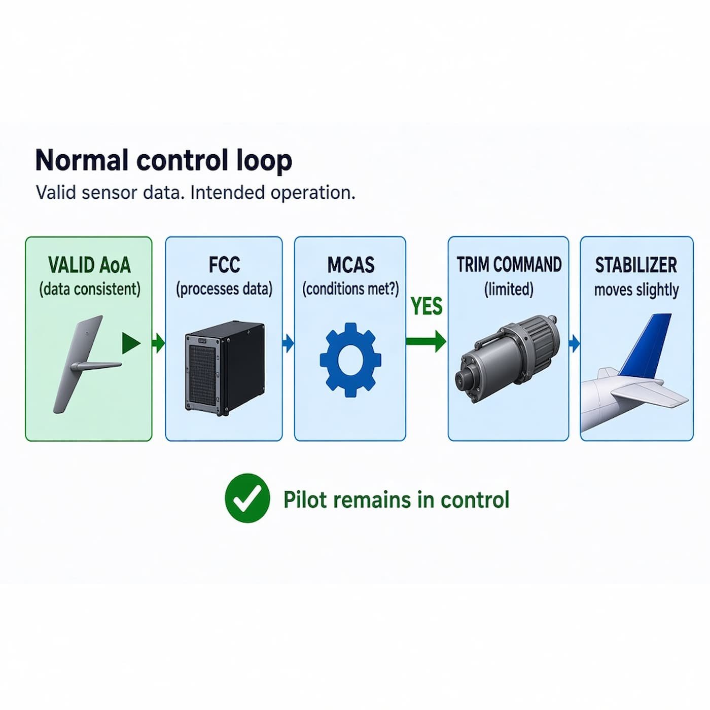
The Boeing 737 MAX was developed as a further evolution of the 737 NG family. The new high-bypass LEAP-1B engines featured a larger fan diameter, requiring them to be positioned higher and further forward relative to the wing compared to previous 737 variants. At high angles of attack, the larger engine nacelles generated additional aerodynamic lift, creating a pitch-up moment. The MCAS function was designed to augment longitudinal handling qualities and ensure required column force gradients at elevated AoA. Importantly, MCAS was not a continuous flight control system; it activated only under specific operating conditions (high AoA, flaps retracted, manual flight).
6. How the Repeated Activation Loop Occurred
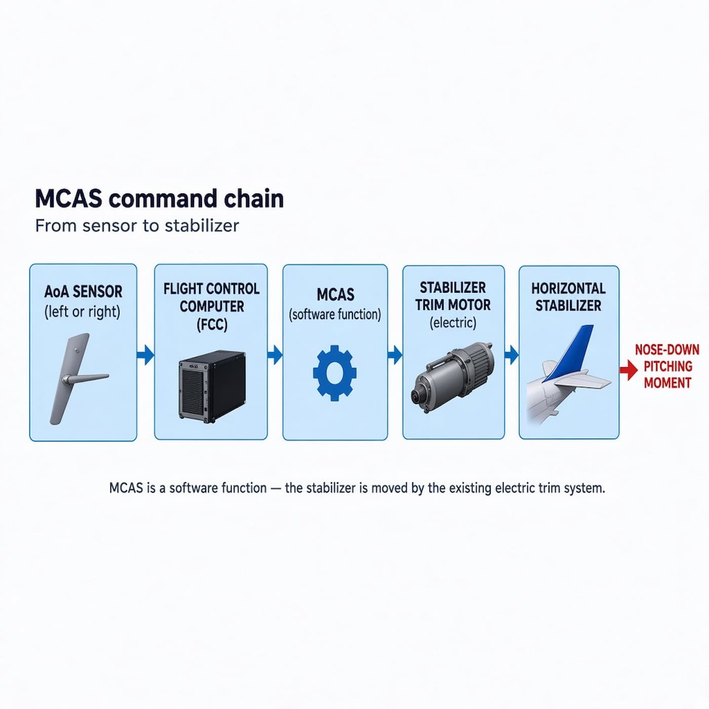
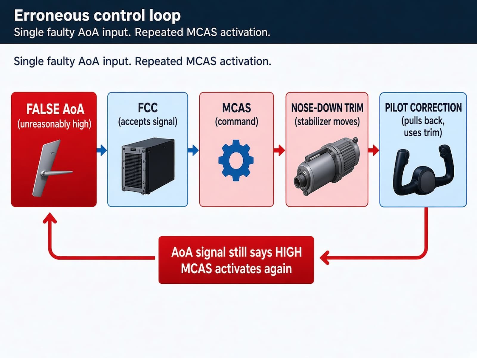
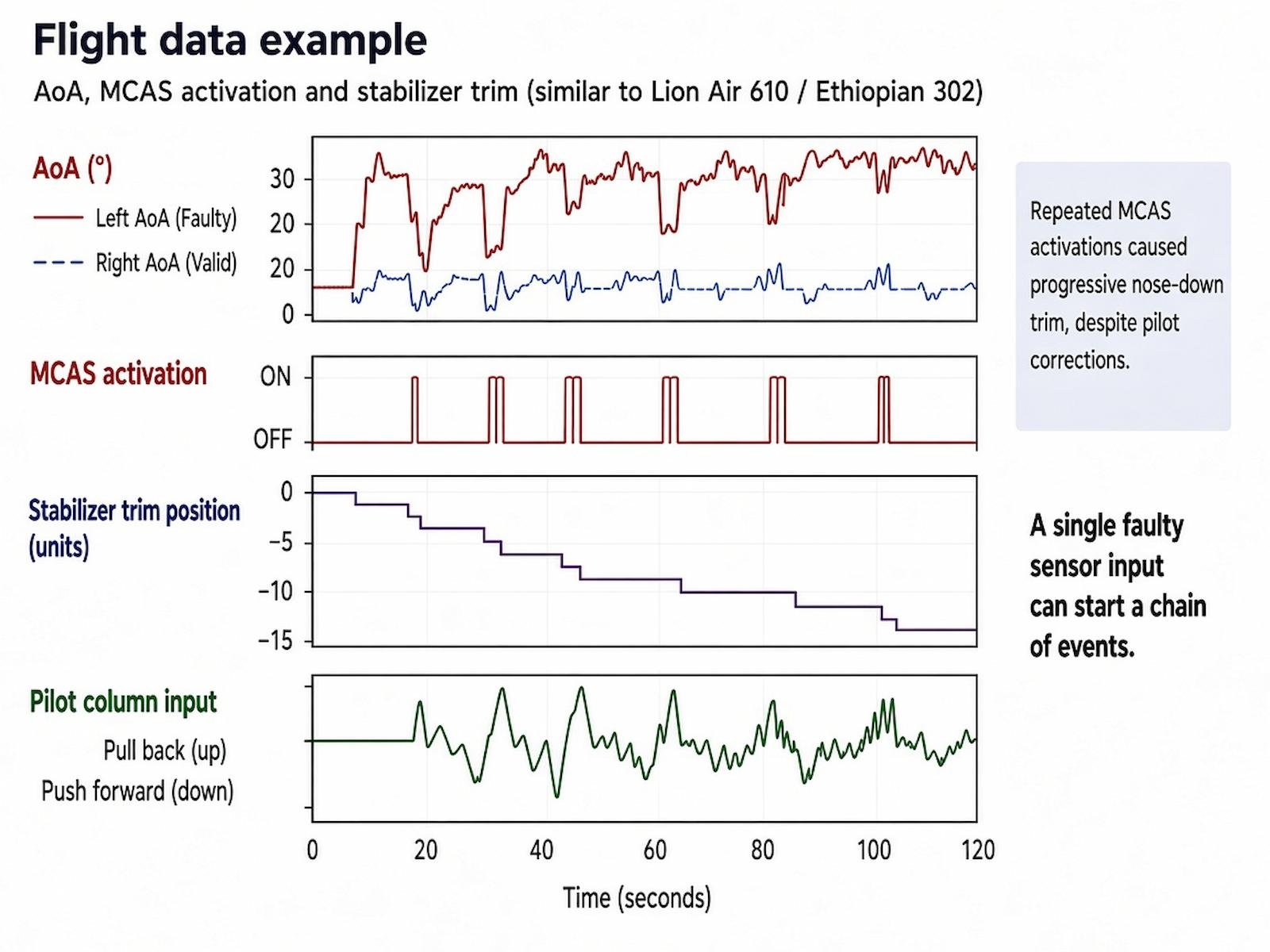
If a single AoA sensor supplied an erroneous high input without cross-channel validation, the flight control system interpreted the data as an impending aerodynamic stall. MCAS commanded the electric stabilizer trim system to move the horizontal stabilizer in the nose-down direction to counter the perceived high AoA. Pilots could counter the resulting pitch change through column inputs and electric trim switches. However, the system did not register manual pilot inputs as evidence that the initial AoA sensor reading was invalid. If activation conditions persisted and the erroneous AoA signal continued, MCAS could re-engage and issue subsequent commands.
7. Why the Flight Crews Faced an Extreme Operational Challenge
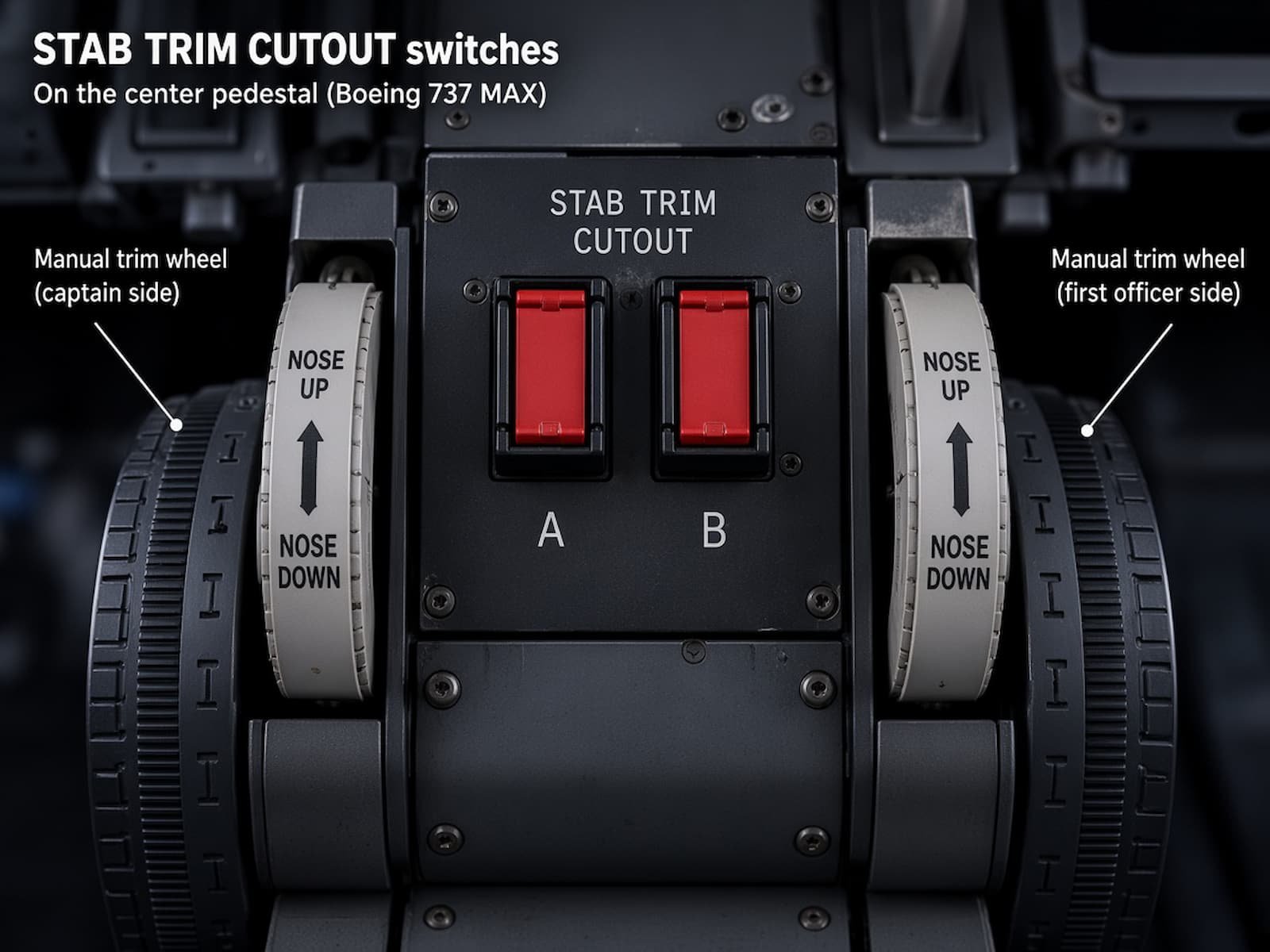
Flight crews encountered a rapid succession of multiple alerts: stick shaker activation, conflicting airspeed and altitude indications, and increasing physical control column forces. Pilots were not adequately informed about the existence and operational logic of MCAS in initial training and flight manual documentation. At high airspeeds and significant mistrim positions, manual movement of the control column and trim wheels required substantial physical force due to high aerodynamic loads. In the event of a runaway stabilizer, the established emergency procedure called for disconnecting electric stabilizer trim using the STAB TRIM CUTOUT switches.
8. Accidents of Lion Air 610, Ethiopian 302 and Systems Engineering Lessons
This sequence of events manifested during Lion Air Flight 610 (October 29, 2018) and Ethiopian Airlines Flight 302 (March 10, 2019). Official accident investigations identified a complex combination of factors: erroneous AoA inputs, MCAS system architecture and logic, alerting and indication design, crew actions, operational procedures, and deficiencies in system development and certification processes. Revised MCAS software mandates cross-comparison of BOTH AoA sensors (disabling the system if a discrepancy exceeds 5.5°). The updated MCAS logic limits activation to a single command per high-AoA event and prevents repeated automatic re-activations based on a continuous false sensor input.